Setup Guide
This is a step-by-step guide to help you configure a flight controller running Betaflight from scratch. Some basic RC knowledge is assumed — if you are completely new to RC aircraft, consider familiarising yourself with fundamentals such as basic controls, soldering, and transmitter operation first. RCGroups and FliteTest are good starting points.
This document is intended as a practical guide, not an authoritative safety checklist. Always exercise common sense, critical thinking, and caution when building and flying RC aircraft.
Hardware
Flight controllers are equipped with accelerometers that are sensitive to shock. Before the FC is mounted on a frame, the bare board has very little mass — a drop or sharp bump applies significant force to the accelerometer and can damage it. Handle the board carefully until it is securely installed on an aircraft.
Before connecting your FC to a computer, plan how you intend to use it. This determines which pads to solder and which features to configure later:
- Read the manual that came with your FC. You can skip the vendor software setup sections — this guide covers that.
- Decide how you will connect your receiver. See the Receiver documentation for the available options.
- Determine how many output pins you need (for ESCs and servos) by reading about Mixers.
- If you want to monitor battery voltage, see Battery Monitoring.
- If you want audible feedback from a buzzer, see the Buzzer documentation.
- If you want your receiver's RSSI forwarded to the FC, see the RSSI documentation.
- If you want GPS-assisted flight (such as GPS Rescue), see the GPS documentation.
- If you plan to use a Blackbox logger, OSD, or telemetry, see the Serial documentation.
Once you know which features and pins you need, solder only what is required to keep the build tidy. Practice on scrap material before soldering the FC itself.
Software Setup
You need the Betaflight Configurator installed on your PC. This is the application used to connect to, configure, and update your flight controller.
Connecting to Your Flight Controller
Once the configurator is installed and open, you will see the welcome screen:

Connect your flight controller to your computer via USB. If successful, a new COM port will appear in the top-right dropdown:
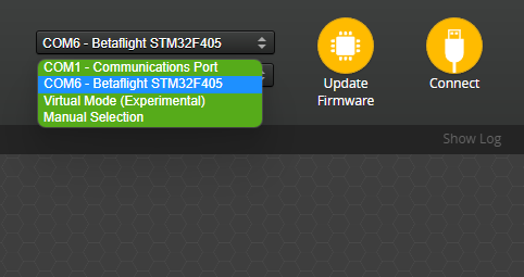
Select the COM port and click Connect.
Not Showing Up/Connecting?
If no new COM port appears, or the configurator cannot connect, try the following:
- Make sure that you are plugging the USB cable into the flight controller, nothing else. Do not connect the Betaflight App to an HD system. Do not connect the Betaflight App to a radio transmitter. the Betaflight App is not meant be used with anything other than a flight controller
- Make sure you are using a USB cable that is capable of data transfer. Some USB cables are only for charging
- You may need to install the drivers for your flight controller. There is a download link for the ImpulseRC Driver Fixer tool in the configurator, or you can download it from the ImpulseRC Driver Fixer repository
- If you are using Linux you may need to add your user to the dialout group and also change udev rules
- If you are still experiencing issues, try shutting down/uninstalling any other software that may be using the COM port. 3d printing software is a common culprit
If you do need to install or reinstall firmware, see the Firmware Installation guide. Otherwise, connect and inspect the existing configuration first — especially on pre-built drones, which are often already configured correctly by the manufacturer.
First Connection and Backup
Once connected, you will land on the Setup Tab. Move the flight controller and confirm the 3D model in the configurator moves accordingly — a good sign that the board is alive and working. From here you can calibrate the gyroscope and accelerometer using the on-screen buttons. Magnetometer calibration is optional and only relevant if your FC has one.
Backup Your Configuration
Before making any changes, back up your current configuration. In the CLI Tab, send either the diff all or dump command, then copy or save the output. This lets you restore the original settings if anything goes wrong.
Receiver Settings
Find which UART your receiver is connected to. A receiver connected to the RX1/TX1 pads is on UART1, RX2/TX2 is UART2, and so on. In the Ports Tab, enable Serial RX on the correct UART.
Do not use the MSP toggle as a general on/off switch for the current UART. Enabling both MSP and Serial RX on the same UART causes a conflict, and the configurator will refuse to save those settings to prevent unintended behaviour.
If your flight controller has a built-in SPI receiver, no UART configuration is needed. Proceed directly to the Receiver Tab setup below.
With Serial RX enabled, open the Receiver Tab and configure the receiver-specific settings:
UART-Based Receivers
Set the Receiver Mode to Serial (via UART) and select the Serial Receiver Provider matching your protocol:
- ELRS / Crossfire / Tracer — CRSF
- FrSky — SBUS or FPort
- Spektrum — Spektrum1024/2048 or Spektrum SRXL2
- FlySky — IBUS
SPI-Based Receivers
Set the Receiver Mode to SPI Rx (e.g. built-in Rx) and select the SPI Bus Receiver Provider:
- ELRS — EXPRESSLRS
- FrSky — FrSky_D (D8), FrSky_X(_LBT) (ACCST D16), FrSky_X_V2(_LBT) (ACCST V2 D16)
- Spektrum — SPEKTRUM
- FlySky — A7105_FLYSKY(_2A)
Once configured, confirm that moving the sticks causes the channel values to update and the 3D model to respond. If channels are misaligned, adjust the Channel Map option.
VTX Settings
In most systems you do not need to configure anything in Betaflight to get basic video working. However, VTX control and HD OSD require additional setup.
Analog VTXs
Analog is the most common video system and generally works without any configuration. If you need to control channel or power level via Betaflight, you need to set up SmartAudio or Tramp. In the Ports Tab, enable SmartAudio or Tramp as a peripheral on the UART your VTX is connected to. Then configure the VTX in the VTX Tab.
You may need a VTX Table for your specific VTX, which can be in two formats:
- CLI Code — Paste directly into the CLI:
# vtxtable
vtxtable bands 5
vtxtable channels 8
vtxtable band 1 BOSCAM_A A CUSTOM 5865 5845 5825 5805 5785 5765 5745 5725
vtxtable band 2 BOSCAM_B B CUSTOM 5733 5752 5771 5790 5809 5828 5847 5866
vtxtable band 3 BOSCAM_E E CUSTOM 5705 5685 5665 5645 5885 5905 5925 5945
vtxtable band 4 FATSHARK F CUSTOM 5740 5760 5780 5800 5820 5840 5860 5880
vtxtable band 5 RACEBAND R CUSTOM 5658 5695 5732 5769 5806 5843 5880 5917
vtxtable powerlevels 5
vtxtable powervalues 25 100 200 400 600
vtxtable powerlabels 25 200 500 1.5 2.5
- JSON — Load or paste into the VTX Table section of the configurator:
Click to expand
{
  "description": "Betaflight VTX Config file for Rush Tank Ultimate",
  "version": "1.0",
  "vtx_table": {
    "bands_list": [
      {
        "name": "BAND_A  ",
        "letter": "A",
        "is_factory_band": true,
        "frequencies": [5865, 5845, 5825, 5805, 5785, 5765, 5745, 5725]
      }
    ],
    "powerlevels_list": [
      {
        "value": 0,
        "label": "25 "
      },
      {
        "value": 1,
        "label": "200"
      }
    ]
  }
}
If you cannot find a preset or a VTX Table, consult your VTX's manual.
If your VTX cannot be set to certain channels or power levels, it may need to be unlocked first. This is usually done by holding the button on the VTX during power-up — tutorials are available online for specific models.
Digital VTXs
Digital VTXs need setup to enable OSD and VTX control. In the Ports Tab, enable VTX (MSP + Displayport) on the UART your VTX is connected to — MSP will be enabled automatically. On versions older than 4.4, enable only MSP and follow the relevant guide.
In the Presets Tab, there are system-specific presets to simplify setup:
- HDZero for 4.2/4.3 and 4.4
- Avatar 4.2/4.3
- FPV.WTF MSP OSD 4.2/4.3
- FPV.WTF + O3 + Avatar for 4.4
For more detail on 4.4 and newer, see the Release Notes.
Motor Settings
In the Motors Tab, set the ESC/Motor Output dropdown to the correct protocol. This is usually DShot300 or DShot600 for most modern ESCs.
- DShot300 is better for slower processors (e.g. F411 boards) and gyros running at 3.2 kHz (e.g. BMI270).
- DShot600 is better for faster processors (e.g. F7 family). Gyros running at 8 kHz (e.g. MPU6000) can take full advantage of this speed.
Using a higher DShot speed than the gyro supports won't cause issues, but won't provide any benefit either.
Remove propellers before testing motors. Plug in a battery, tick the confirmation checkbox, and slowly raise the Master slider. The motors may stutter slightly at very low values but should spin smoothly at slightly higher values. Verify that all motors spin in the correct direction as set by the Motor direction is reversed toggle (Props In vs. Props Out):
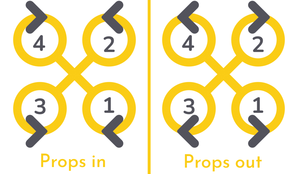
If a motor spins in the wrong direction, reverse it in the Motor direction sub-menu. If the motor numbers do not match the diagram, remap them.
Mode Settings
Modes let you change quadcopter behaviour in flight by assigning AUX channel switches as inputs. In the Modes Tab you will find all available modes.
The only mode you strictly need is ARM:

ARM activates the PID loop and allows the motors to spin. To assign it:
- Click Add Range — this creates a range slider tied to an AUX channel. The mode is active when the channel value falls within the range.
- The
AUTOdropdown auto-selects the AUX channel when you flip the switch you want to use. Flip it now and the dropdown updates automatically. You can also select the channel manually. - Move the range slider so it covers the indicator when the switch is in the arm position.
Recommended additional modes:
-
BEEPER— Activates the beeper and/or motor beeping to help locate a downed quad. -
ANGLE— A self-levelling mode useful for beginners or as a recovery aid.tipThe default flight mode is Acro (also called Rate mode): stick position controls the rate of rotation of the quad. This is the standard mode for most flying, and any other flight mode overrides it.
Angle mode holds the aircraft at the angle commanded by the sticks rather than rotating it, and is useful for beginners or structured practice.
-
FLIP OVER AFTER CRASH— Reverses the motors to flip the quad upright after a crash.dangerThis puts extreme stress on motors and ESCs when the motors are obstructed after a crash. Only use it when you are confident it is safe to do so.
OSD Settings
The OSD overlays flight information on your video feed. In the OSD Tab, you have a list of elements on the left and three checkbox columns — one per OSD profile. OSD profiles let you switch between different layouts in flight.
Enable an element's checkbox to add it to the corresponding profile. Enabled elements appear in the preview and can be dragged to reposition them. Some elements have additional settings such as units, timer source, or warning thresholds.
At minimum, enable:
Warnings— Alerts for low battery, low RSSI, and other critical conditions.Battery average cell voltage— Shows per-cell voltage regardless of pack size.- One of
Link quality,RSNR Value,RSSI Value, orRSSI dBm Value— Choose the metric your radio system supports (check the manufacturer's documentation).
Final Testing and Safety
Before flying, verify that your aircraft is correctly configured. Do not skip these steps — a misconfigured quad can fly away or cause harm to people and property.
- Read the Safety documentation before doing anything else.
- Learn how to arm and disarm the FC, and review the Controls documentation.
- Set up Failsafe properly. Take your time and do it right.
- On the bench, without propellers: confirm that Failsafe triggers as configured.
- Test aileron and elevator input on the transmitter: does the aircraft respond in the correct direction?
- Without propellers, throttle at approximately 30%: tilt the aircraft — do the motors momentarily compensate for the tilt, simulating a wind gust correction?
- In ANGLE mode, without propellers, throttle at approximately 30%: tilt the aircraft so one motor points toward the ground — does that motor spin up and stay at high RPM until the craft is levelled again?
If any of these tests fail, do not attempt to fly. Return to the relevant configuration steps, check for reversed channels, and verify that the board orientation is set correctly.
Ready to Fly!
With everything configured and tested, do a final check that all settings look correct, then do a quick hover test to confirm everything works as expected.
If something is not working, review this guide for common mistakes. You can also check the troubleshooting page for additional solutions. If you are still stuck, ask in the Betaflight Discord.
Advanced Topics
Once you are comfortable with the basics, explore these additional features and guides: